Table of Contents:
- Introduction to Engineering Drawing
- Types of Engineering Drawings
- Tools and Techniques for Engineering Drawing
- Standards and Conventions in Engineering Drawing
- Applications of Engineering Drawing
- Advancements in Engineering Drawing
- Careers in Engineering Drawing
- Conclusion
-
1.Introduction to Engineering Drawing
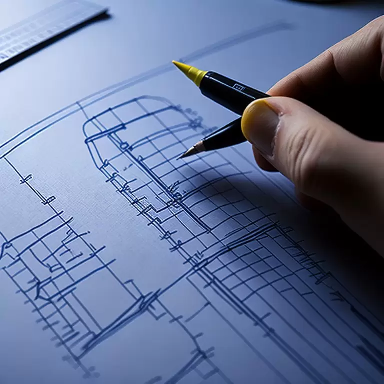
Engineering drawing is a specialized form of technical drawing used by engineers and designers to communicate critical details of a design project to other professionals or manufacturers. An engineering drawing typically includes detailed information such as dimensions, materials, and technical specifications required to manufacture, build or construct a product, part, or structure.
The origins of engineering drawing can be traced back to ancient times when architects and builders would use drawings to communicate design ideas and construction details. In the modern era, engineering drawing has evolved to become a universal language used by engineers and designers to collaborate and communicate effectively, regardless of language or cultural barriers.
The importance of engineering drawing today is rooted in its versatility and specificity. An engineering drawing conveys a wide range of detailed information that’s critical in the design process. Without it, manufacturing and construction of complex products, machinery and infrastructure would be difficult, if not impossible, to achieve with accuracy and quality.
In today’s digital age, engineering drawing has undergone a significant transformation, making it easier to share, collaborate and access technical plans and documents in real-time. The ability to create and share 3D models, virtual prototype simulations, and computer-aided design (CAD) models means that engineering drawing is more powerful than ever.
In summary, engineering drawing is a vital component of modern design, enabling engineers, architects, and designers to communicate their ideas and designs effectively. With the rapid advancements in technology and the emergence of new tools, we can expect to see significant improvements as we continue to develop more elaborate designs using engineering drawing technologies.
-
2.Types of Engineering Drawings
Engineering drawings are created using various projection methods to communicate a design. These projection methods are essential in technical drawing because they help design professionals and manufacturers understand the size, shape, and configuration of a design accurately. Here is an overview of the different types of engineering drawings:
1.Orthographic Projection
Orthographic projection is a type of technical drawing that displays a three-dimensional object in two dimensions, and it is the most commonly used technique in the engineering industry for design communication. Also known as multiview projection, the orthographic projection shows an object in several views, with each view displaying the object from a different angle. Orthographic projection is used to represent objects accurately, showing all dimensions clearly and proportionally.
2.Isometric Projection
Isometric projection is a type of technical drawing that represents a three-dimensional object using a single, rotated view of the object. In isometric projection, the object is rotated 45 degrees on both the horizontal and vertical axes to maintain the original proportions of the object. Isometric projection simplifies the visual representation of an object with complex geometry, making it easier to understand the design.
3.Oblique Projection
Oblique projection is a type of technical drawing that represents an object in two-dimensional space. In oblique projection, the front face of the object is drawn parallel to the picture plane, while the top face of the object is rotated to a certain degree for clarity of view. Oblique projection is used for objects with rectangular or cubic shapes.
4.Perspective Projection
Perspective projection is a type of technical drawing that represents an object in a realistic, three-dimensional view with depth, height, and width. In perspective projection, the object is represented as it appears to the human eye, with the relative size and appearance of the object being drawn accurately to the viewer’s perspective. Perspective projection is primarily used for presenting a design to clients or stakeholders, as it provides a more compelling and realistic view of the object or structure.
In summary, there are many different types of engineering drawings that are used to communicate a design, with each technique having its unique benefits depending on the intended application. Orthographic projection, isometric projection, oblique projection, and perspective projection are the most commonly used methods in today’s industry. Understanding the strengths and weaknesses of each method is essential in creating technical drawings that can accurately convey the necessary information to others in the design process.
-
3.Tools and Techniques for Engineering Drawing
Engineering drawing can be created using a wide range of tools and techniques, from traditional drafting tools to state-of-the-art digital software. Here is an overview of the different tools and techniques used in engineering drawing:
1.Traditional Drafting Tools
Traditional drafting tools are the old-school way of creating technical drawings using pencils, compasses, protractors, and other tools. These tools are still used today by many designers to create hand-drawn sketches that convey design ideas quickly and efficiently. Traditional drafting tools can be used to create technical drawings on paper, vellum, or other media. The use of these tools requires a high level of skill and precision for creating accurate and detailed designs.
2.Computer-Aided Design (CAD) Tools
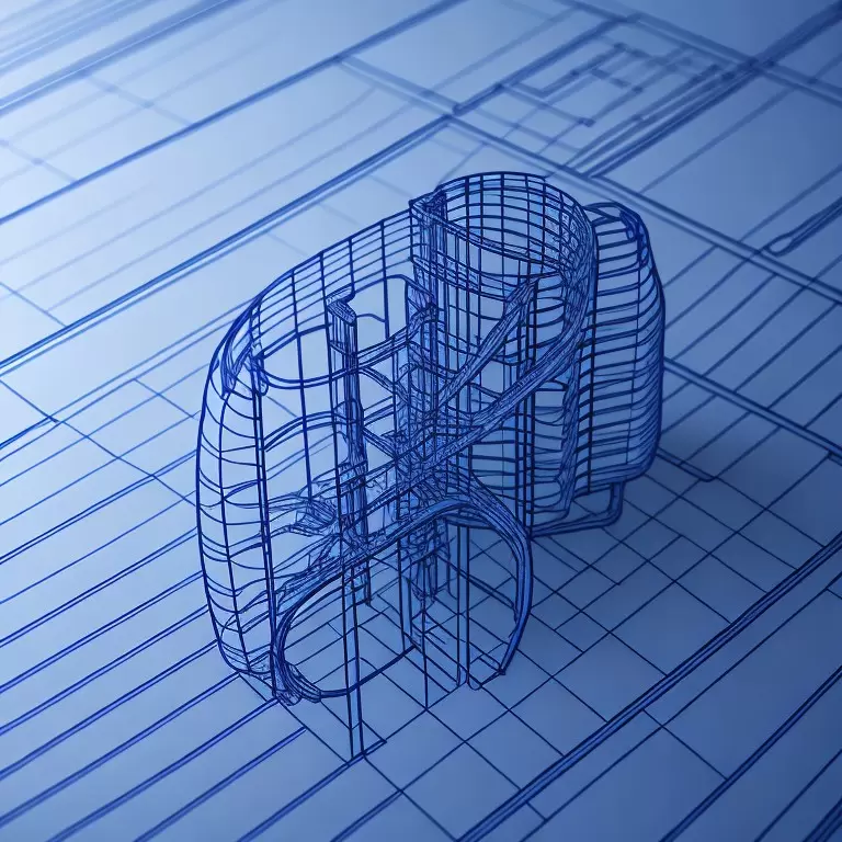
CAD tools revolutionize the technical drawing process by digitizing the entire design process. CAD software allows designers to create and modify digital drawings much faster and more accurately compared to traditional drafting tools. Programs such as AutoCAD, SolidWorks, and Fusion 360 have become industry standards for creating 2D and 3D models that can be easily manipulated and shared across platforms. CAD software also includes features such as automated dimensioning, rendering, and analytics tools that simplify the process of creating more complex designs.
3.Best Practices for Drafting and Design
Best practices for drafting and design involve creating accurate, easy-to-read technical drawings that are easy for other professionals to understand. The best practices include using standard dimensions, labeling and annotations, and leveraging CAD tools to maintain consistency throughout the design process. Other essential best practices include adhering to industry-specific drafting standards, communicating design intents, and ensuring accuracy with methods such as dimensioning, tolerance analysis, and quality control.
In summary, traditional drafting tools and CAD software have their unique strengths and weaknesses, and their popularity has varied throughout the years of design history. By maintaining best practices for drafting and design and selecting the right tools and techniques, engineering professionals can create technical drawings that are concise, accurate, and easy to understand.
-
4.Standards and Conventions in Engineering Drawing
Engineering drawing follows strict standards and conventions to ensure clear communication and understanding of technical information. Here are the different types of standards and conventions in engineering drawing:
1.International Standards
There are several international standards set to standardize engineering drawing practices, which include geometrical dimensioning and tolerancing (GD&T), notation, and precision. The International Organization for Standardization (ISO) is the primary agency responsible for creating engineering standards. ISO 128 is a widely used standard that regulates general principles of presentation for technical drawings.
2.Industry-Specific Standards
Different industries have specific standards for engineering drawings. For instance, the American Society of Mechanical Engineers (ASME) created the ASME Y14.100-2013 standard for engineering drawing practices, which provides guidance on how to produce and interpret drawing standards in the engineering field. Industry-specific standards such as ASME Y14.100-2013 can vary significantly from one industry to another, preventing confusion and misunderstandings in technical communication.
3.Common Conventions and Symbols
There are a few essential conventions and symbols that are commonly used in engineering drawing, including:
- Hidden lines: represent features that cannot be seen from a specific direction
- Centerlines: represent the center of circular features such as holes and cylinders
- Section lines: represent an imaginary cut through a part
- Arrowheads: used to indicate the direction of measurement or indicate movement/direction
- Dimension lines: indicate the size of a feature
Another example of commonly used conventions in engineering drawing is the use of different line weights to convey information, such as thick lines represent borders and outlines, while thin lines represent other portions of the design.
In summary, adhering to standards and conventions is crucial in engineering drawing because it ensures accurate communication and understanding of technical details among professionals. By using international standards, industry-specific standards and conventions, and commonly used symbols and categories help ensure seamless technical communication with less room for confusion or error.
-
5.Applications of Engineering Drawing
Engineering drawings have a wide range of applications in various industries, from product design and development to architecture and construction. Here are some of the most common applications of engineering drawing:
1.Product Design and Development
Engineering drawings are an essential aspect of product design and development as the designers use engineering drawings to clarify the design specifications, product features, and other necessary details required to convey the intended design. They provide a clear and specific definition of the product’s dimensions, materials, construction, and requirements necessary for production. Details of the design are outlined in the specifications, allowing accurate reproduction by third-party parties, and like the manufacturers, suppliers, and developers. Engineering drawings enable all parties involved in the design and production process to communicate effectively and collaboratively, reducing errors and time-to-market
2.Manufacturing and Production
In a manufacturing environment, the use of engineering drawings is necessary to ensure the proper construction of components, machinery, and other engineering products accurately. The drawings are typically used to make production patterns, molds, jigs, and fixtures that ensure identical production every time, reducing defects and time wastage. Similarly, technicians, operators, and machine operators can quickly interpret and implement the necessary instructions and dimensions to produce high-quality components, machines and products.
3.Architecture and Construction
In architecture and construction fields, engineering drawings are used extensively to describe the structure, design, and construction details of various buildings, bridges, roadways, and infrastructure. The engineering drawings provide essential details of the dimensions, design and structural requirements of the buildings and the corresponding equipment necessary for their successful construction. Architects, contractors, and engineers use these drawings to ensure that the construction meets safety and regulatory standards, and the necessary equipment and tools are acquired to complete the project successfully.
4.Aerospace and Defense
In the aerospace and defense industry, engineering drawings are integral in creating designs for advanced aircraft, spacecraft, and other high-tech technologies. Engineers use the drawings to provide clear, technical specifications for the components, computer hardware, and software required for each system’s successful operation, avoiding havoc during operation. Designers and manufacturers use various engineering drawings such as structural drawings, stress analysis, electrical and instrumentation drawing, cleaning, and painting drawing, among others.
In summary, engineering drawings serve as critical components to various applications in different industries such as product design and development, manufacturing and production, architecture and construction, aerospace and defense. By communicating technical specifications and details clearly and precisely, engineering drawings prevent costly mistakes, promote efficiency and accuracy, and improve quality assurance.
-
6.Advancements in Engineering Drawing
Engineering drawing has come a long way since the days of traditional drafting tools. Advancements in technology have revolutionized the way we create, communicate, and execute designs. Here are some of the significant advancements in engineering drawing:
1.3D Modeling and Simulations
3D modeling software tools now make it possible to create computer-generated models of complex designs and structures. Modeling software provides real-time feedback and simulations of designs in virtual reality. This allows designers to evaluate and test their designs, optimizing their components and systems, detecting and solving potential problems, and enhancing their overall design in a virtual environment.
2.Virtual and Augmented Reality
Virtual and augmented reality (VR/AR) tools enable engineering professionals to experience their designs from within a simulated space, allowing designers to conduct simulations with unique characters, allowing detailed visualizations of designs and virtual evaluations of different systems components. With VR/AR, designers can work with realistic simulations of various aspects of their designs, making it easier to detect errors and optimize the design without building prototypes or physical models.
3.Artificial Intelligence and Automation
Artificial intelligence and automation are bringing a whole new era of engineering design with robotic processes like machining, drilling and cutting, and some industrial practices performed more efficiently, effectively and at a lower cost with automated or semi-automated processes. Intelligent systems can automatically generate designs based on engineers’ inputs, analyze and find flaws in existing designs, predict outcomes and performance, allowing faster and more accurate evaluations of designs.
In summary, the recent advancements in engineering drawing, those in 3D modeling, virtual, and augmented reality, artificial intelligence and automation have reshaped the industry’s direction. These technological developments have succeeded in promoting a highly accurate and advanced engineering design, facilitating more efficient communication and problem-solving of design issues, ultimately enabling engineering professionals to create cost-effective, functional, and highly successful products.
-
7.Careers in Engineering Drawing
Engineering drawing is a vital aspect of the engineering industry, with various careers involving technical drawing and design. Here are some of the industries and careers that involve engineering drawing:
1.Drafters and Designers
Drafters and designers are professionals involved in creating technical drawings using traditional drafting tools or computer-aided design software. They typically support engineers and architects by creating detailed drawings and illustrations of their designs, including mechanical parts, electrical wiring, plumbing systems, architecture, and structures, among others.
2.Engineers and Architects
Engineers, architects, and other design professionals use engineering drawings as visual representations of their designs. They use technical drawings to communicate their designs to drafting or design teams, ensuring the designs are interpreted accurately, and effectively work with these teams to implement or recommend changes to the designs. These professionals heavily rely on technical drawings for succeeding in design analysis, testing, and optimization, promoting design efficacy and performance.
3.Educators and Trainers
Educators and trainers may design and create educational materials for engineering drawing courses, tutorials, or training programs. They may teach a wide range of design skills to individuals in various fields such as architecture, engineering, or manufacturing applications. As computer-aided design programs continue to become more complex, the demand for knowledgeable educators and trainers in drafting and design will continue to rise.
Overall, engineering drawing remains a crucial component of the engineering industry, providing critical support through aiding in communication with other professionals during design analysis, testing and manufacturing, allowing confidence in cost-effectively and high-quality designs.
If you need more the information ,You can click on the V1 Prototype website to find it.
-
8.Conclusion
In conclusion, engineering drawing is an essential component of the engineering industry, serving as a primary means of communication amongst with engineers, designers, manufacturers, contractors and other professionals. The technical drawings and models created serve as virtual 3D models or blueprints that enable effective design communication, simulation, and testing. This, consequently, streamlines design optimization, reducing the time, cost, and resources required to bring a project from conception to fruition.
The key points from our discussion include the various tools and techniques used in engineering drawing, such as traditional drafting tools, computer-aided design (CAD) tools, and industry standards like ISO and ASME. We also highlighted the various essential applications of engineering drawing, such as manufacturing, product design and development, architecture and construction, and aerospace and defense.
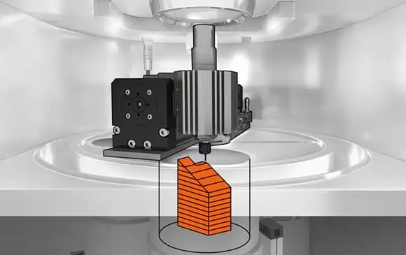
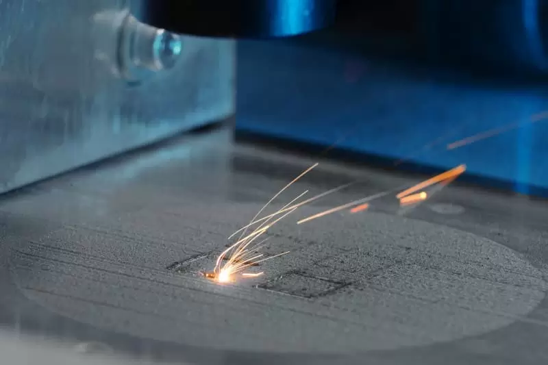
The future prospects of engineering drawing and design continue to change rapidly with continued technological innovations, such as 3D printing, machine learning, and the use of Virtual and Augmented Reality. These advancements have the potential to increase design efficiency, improve product quality, facilitate rapid prototyping, shorten time-to-market, and enhance technical communication among professionals around the globe.
In conclusion, the precision, accuracy, and efficiency of engineering design and drafting continue to support significant industry strides like Industry 4.0 initiatives as it evolves. As these technologies become more advanced, engineering drawing and design will continue to transform the manufacturing and production processes into simpler, scalable operations, with the potential to support various areas of life and industries around the globe.
